SOFTWARE AND DATA PIPELINE

    1.  Data Flow Overview

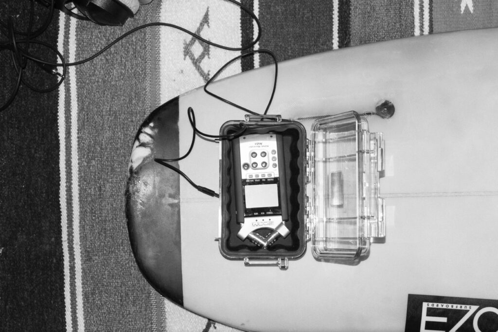
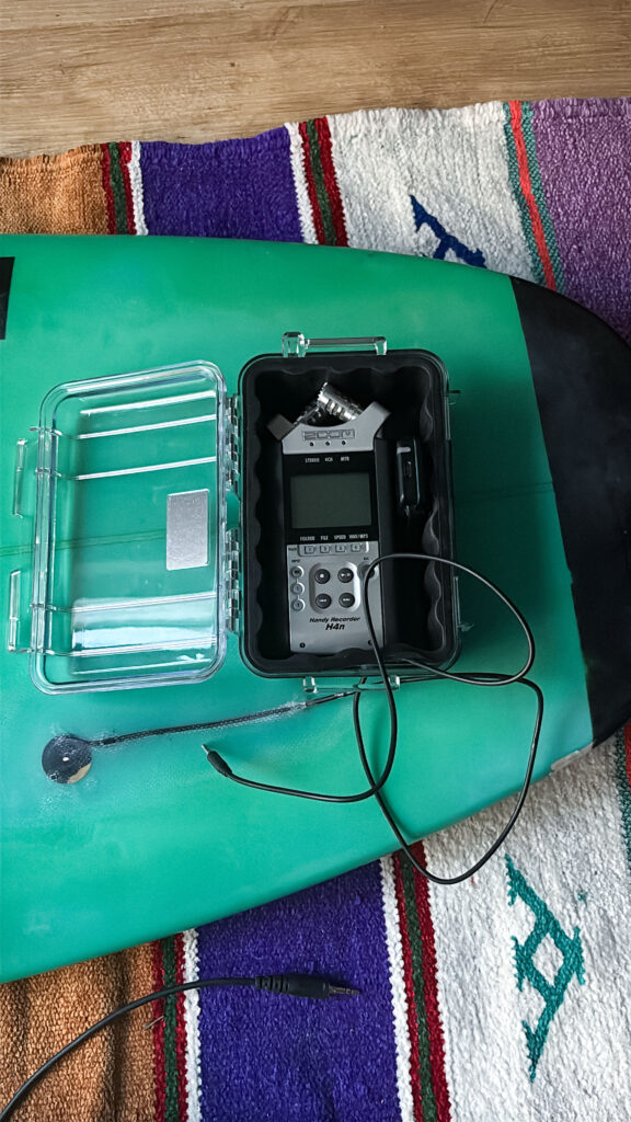
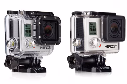
The data pipeline is structured in three different phases: acquisition, post-processing, and sonification. The first part, Acquisition includes independent capturing of audio (Zoom H4n, contact microphone), motion (x-IMU3), and video/audio (GoPro Hero 3). Then, in the next step, post-processing uses the x-IMU3 SDK to decode the recorded data. This data is then send via OSC to Pure Data and is there translated into its different parameters. 

The sonification and audio transformation are carried out also using Pure Data.

This architectural structure supports a secure workflow and easy synchronization in post.

  1. Motion Data Acquisition

Motion data was recorded onboard the x-IMU3 device. After each session, files were extracted using the x-IMU3 GUI and decoded into CSVs. These contain accelerometer, gyroscope, and orientation values with timestamps (x-io Technologies, 2024). Python scripts parsed the data and prepared OSC messages for transmission to Pure Data. The timing issue is faced with the help of synchronizing big movements in rotation or acceleration during the long recording all devices. (Wright et al., 2001).

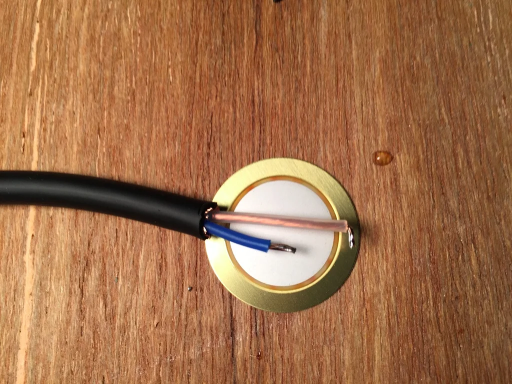
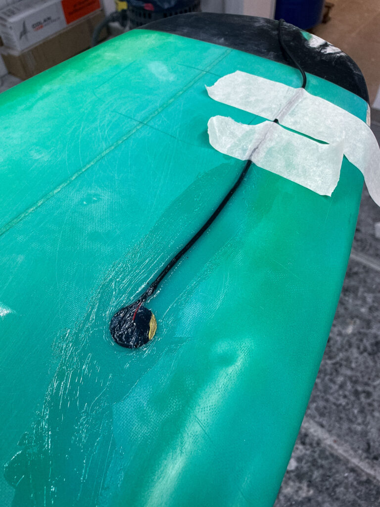
The Audio recorded from the contact mic is a simple mono WAV file and is Pure Data and later Davinci Resolve for the audio video final cut. Looking at the recordings, the signal primarily consisted of strong impact sounds, board vibrations, water interactions and movements of the surfer. These recordings are used directly for the sound design of the movie. During the main part of the movie, when the surfer stands on the board, this audio will also be modulated using the motion data of the sensor reflecting on the gestures and board dynamics. (Puckette, 2007; Roads, 2001).

  1. Video and Sync Reference

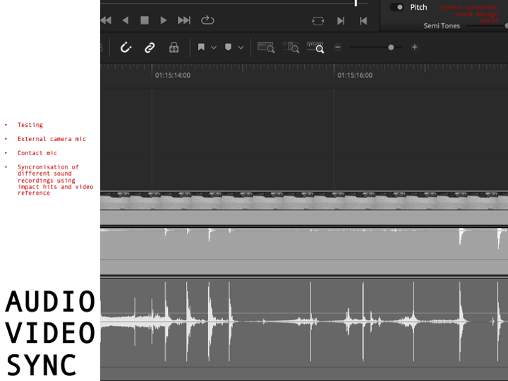
Having all this different not in synchronized time recorded data files leaves a great question of exact synchronization. Therefore, a test was conducted which will be explained in more detail in the section: 10. SURF SKATE SIMULATION AND TEST RECORDINGS. The movement of surfing was simulated using a surf skateboard, on which a contact microphone was mounted on the bottom of the deck. In addition to the microphone also the motion sensor was placed next to the microphone. Now, having the image and the two sound sources (contact microphone and audio of the Sony camera) I could synchronize both recordings in post-production using Davinci Resolve. Here the main key findings were the importance of great labeling of the tracks and clear documentation of each recording. During the final recordings on the surfboard the GoPro Hero 3 will act as an important tool to synchronize all the different files in the end. Another audio output of the GoPro acts as an additional backup for a more stable synchronization workflow. Here test runs on the skateboard are essential to be able to manage all the files in post-production later.  (Watkinson, 2013).

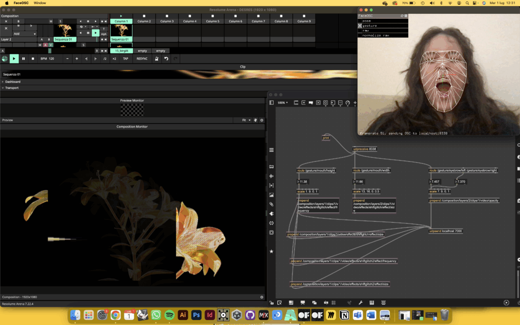
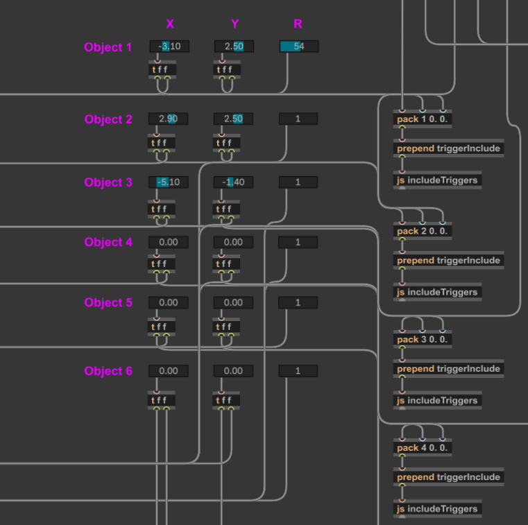
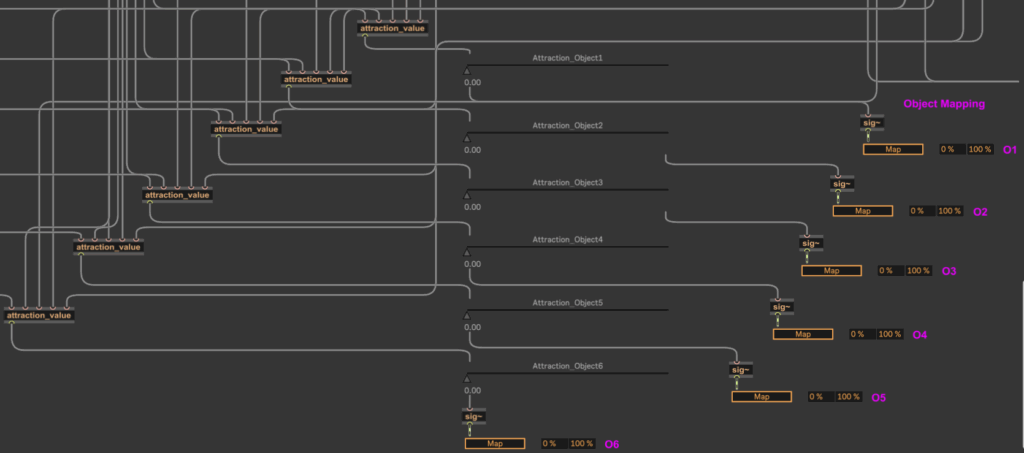
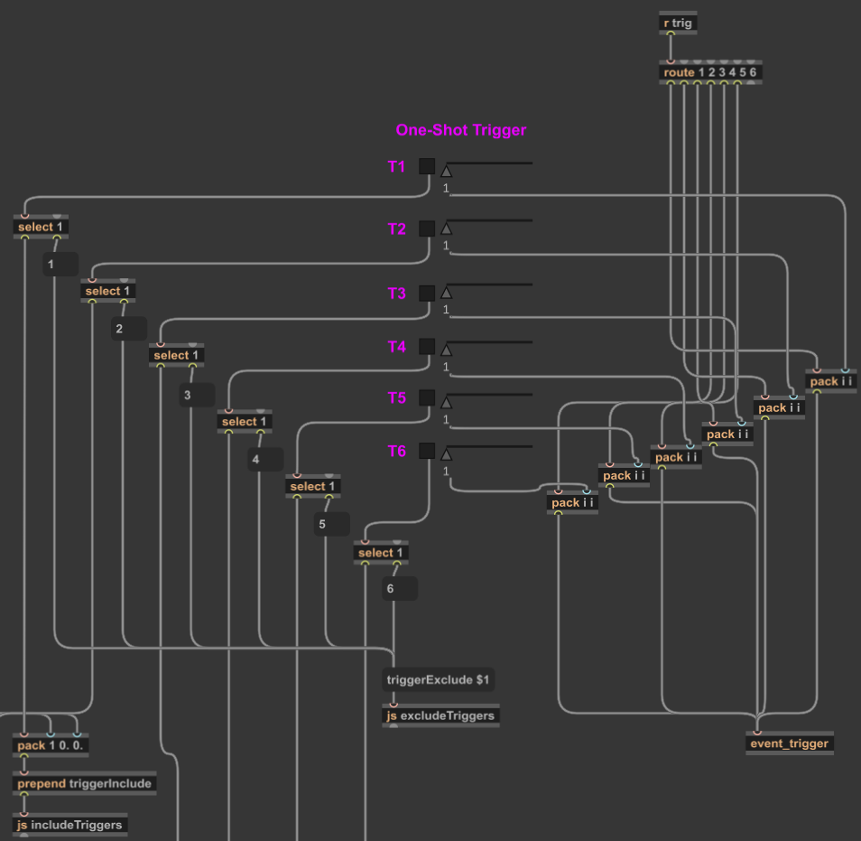
The motion data recorded on the ximu3 sensor is replayed on the GUI of the sensor and can then send the data via OSC to Pure Data. Parameters such as pitch, roll, and vertical acceleration can then be mapped to different variables like grain density, stereo width, or filter cutoff frequency. (Puckette, 2007).

  1. Tools and Compatibility

All tools are selected based on compatibility and possibility to record under this special conditions. The toolchain includes:

  • x-IMU3 SDK and GUI (macOS) for sensor decoding
  • Python 3 for OSC streaming and data parsing
  • Pure Data for audio synthesis
  • DaVinci Resolve for editing and timeline alignment

This architecture functions as the basic groundwork of the project setup and can still be expanded using different software’s of python code to add more individualization during different steps of the process. (McPherson & Zappi, 2015).

  1.  Synchronization Strategy

Looking deeper into the Synchronization part of the project, challenges arrise. Because there is no global time setting for all devices, they have to run individually and then be synchronized in post-production. Here working with good documentation and clear labels of each track helps to get a good overview. Especially the data of the motion sensor will have a lot of information and needs to be time aligned with the audio. Synchronizing audio and video, however, is for sure a smaller challenge, because of the multiple different audio sources and the GoPro footage. A big impact or a strong turn of the board can then be mapped to the audio and video timeline. The advantage of one long recording of a 30 min surf session is for sure, that the possibility for such an event increase over time. Tests with the skateboard, external video and audio from the contact microphone were already successful.


On the image the setup in Davinci Resolved shows the synchronization of the contact microphone (pink) and the external audio of the Sony Alpha 7iii (green). Here the skateboard was hit against the floor in a rhythmical pattern, creating this noticeable spikes in audio on both devices. This rhythmical movement can also be seen on the XIMU3 sensor. 

HARDWARE SYSTEM SURFBOARD


  1. 1.1. OVERVIEW OF THE SETUP
    The hardware setup of this project was developed to function and withstand under the challenging environmental conditions typical for surfing. Therefore, the full equipment needs to not only be made for saltwater exposure, but also be strong enough to handle strong hits and impacts. The sunlight, and hot temperatures also act as another impactor. Therefore, building components were selected based on their stability, mobility, and compactness. The complete system includes a waterproof Pelican 1050 case mounted on the surfboard, containing a Zoom H4n audio recorder, a piezoelectric contact microphone and an x-IMU3 motion sensor. An externally mounted GoPro Hero 3 camera records video and sound. The interior of the Peli case is filed with protective foam to minimize shock and mechanical disturbance. Concluding, the arrangement was optimized to allow a smooth operation during surfing while maintaining robust data acquisition.

1.2. MOTION SENSOR – X-IMU3

The x-IMU3, was developed by x-io Technologies. It is a compact inertial measurement tool (IMU) capable of logging tri-axis accelerometer, gyroscope, magnetometer and orientation data with timestamp precision. For this application, the sensor operated in standalone mode and will be charged by an external small power bank later retrieval. After each recording session, the x-IMU3 GUI and SDK were used to decode. ximu3 binary files into structured CSV datasets (x-io Technologies, 2024). These data streams are then available for the synchronization part with audio and video recordings. Furthermore, these recorded values will be used to manipulate the recorded audio using Pure Data.

The x-IMU3 sensor was selected due to its reliability, sampling rate of up to 500 Hz, and OSC-compatible output structure. This enables later integration with sound synthesis software’s in the later process. The sensor is placed in the box cushioned within protective foam in the Pelican case to minimize noise artifacts caused by board vibration.

1.3. CONTACT MICROPHONE – PIEZO DISC
In order to add another dimension to the sound recording by capturing board vibrations and internal mechanical changes, a piezoelectric contact microphone was mounted beneath the surfboard wax layer, at the right side of the nose, near the front foot position. Unlike traditional microphones, piezo elements record vibrations through physical material contact, making them suitable for capturing impactful sound events. Also, due the good implementation movements of the surfer on the board are recorded very well. The sensor is routed to the case using a sealed cable channel and insulation to prevent water from getting in the box or inside the board.
This microphone setup allows for the recording of impactful events such as hits, flex, and frictional interactions between the board, the water and the surfer. These signals, together with the recordings of the zoom, form the primary audio source used in the sonic interpretation of the surf session. This implementation of a piezo mic in a surfboard has not been done or documented before and is therefore an innovative approach which is of course interesting for sound engineers, as well as surfers and surfboard builder (Truax, 2001).

1.4. AUDIO RECORDER – ZOOM H4N
The audio data was recorded using a Zoom H4n Handy Recorder, configured to capture a mono signal from the contact microphone. The recorder was selected for its portability, sound quality (24-bit/44.1 kHz), and dual XLR/TRS inputs. It was housed inside the Pelican case using closed-cell foam to dampen mechanical noise. Battery-powered operation and SD card storage enabled autonomous recording during mobile sessions.
Gain levels were calibrated before each session to preserve signal integrity and prevent clipping. The system was designed to ensure consistent signal acquisition even under dynamic surf conditions (Zoom Corporation, 2023).

1.5. VISUAL SYNCHRONIZATION – GOPRO HERO 3
To also have a video output of the surf session, GoPro Hero 3 camera is mounted at the board’s nose. This video material served as both documentation and reference for synchronization. Here, the synchronization of different audio sources and the sensor data is challenging but will made easier with having audiovisual references. For example, a double tapping on the board can help synchronize image to sound. The GoPro’s audio, while limited in quality, served as another layer reference for alignment.
In addition, the video recordings serve also as a tool to analyze body posture, movement patterns, and spatial context (Watkinson, 2013). The surf movie will be consisting of many shots taken by the GoPro and will support the surf film with an immersive camera angle.


1.6. ENCLOSURE AND MOUNTING
– PELICAN CASE 1050
The Zoom Recorder, sensor, power bank and cables of the contact microphone are enclosed in a Pelican 1050 Micro Case. This model was selected for its IP67-rated waterproof sealing, shock resistance, and small form, making it not too bulky on the board, but still big enough to fit all the necessary equipment.
Moving forward, the case is mounted to the surfboard using strong glue and surfboard wax and is incorporated in the general body of the board. In order to connect the contact microphone from outside to the inside, one hole was made in the box. This hole is again sealed with silicone caulk to make it leak and saltwater proof.

Inside, the box a special Peli foam is inserts to prevent internal motion and a fixation for the sensor and the recorder.
The case and cabling configuration underwent field testing, including simulated riding on a surf skate and controlled submersion for a specific amount of time, to ensure no leakage will occur during recording

Post 1: Listening to the Ocean

– The Emotional Vision Behind Surfboard Sonification

Surfing is more than just a sport. For many surfers, it is a ritual, a form of meditation, and an experience of deep emotional release. There is a unique silence that exists out on the water. It is not the absence of sound but the presence of something else: a sense of connection, stillness, and immersion. This is where the idea for “Surfboard Sonification” was born. It began not with technology, but with a feeling. A moment on the water when the world quiets, and the only thing left is motion and sensation.

The project started with a simple question: how can one translate the feeling of surfing into sound? What if we could make that feeling audible? What if we could tell the story of a wave, not through pictures or words, but through vibrations, resonance, and sonic movement?

My inspiration came from both my personal experiences as a surfer and from sound art and acoustic ecology. I was particularly drawn to the work of marine biologist Wallace J. Nichols and his theory of the “Blue Mind.” According to Nichols, being in or near water has a scientifically measurable impact on our mental state. It relaxes us, improves focus, and connects us to something larger than ourselves. It made me wonder: can we create soundscapes that replicate or amplify that feeling?

In addition to Nichols’ research, I studied the sound design approaches of artists like Chris Watson and Jana Winderen, who work with natural sound recordings to create immersive environments. I also looked at data-driven artists such as Ryoji Ikeda, who transform abstract numerical inputs into rich, minimalist sonic works.

The goal of Surfboard Sonification was to merge these worlds. I wanted to use real sensor data and field recordings to tell a story. I did not want to rely on synthesizers or artificial sound effects. I wanted to use the board itself as an instrument. Every crackle, vibration, and movement would be captured and turned into music—not just any music, but one that feels like surfing.

The emotional journey of a surf session is dynamic. You begin on the beach, often overstimulated by the environment. There is tension, anticipation, the chaos of wind, people, and crashing waves. Then, as you paddle out, things change. The noise recedes. You become attuned to your body and the water. You wait, breathe, and listen. When the wave comes and you stand up, everything disappears. It’s just you and the ocean. And then it’s over, and a sense of calm returns.

This narrative arc became the structure of the sonic composition I set out to create. Beginning in noise and ending in stillness. Moving from overstimulation to focus. From red mind to blue mind.

To achieve this, I knew I needed to design a system that could collect as much authentic data as possible. This meant embedding sensors into a real surfboard without affecting its function. It meant using microphones that could capture the real vibrations of the board. It meant synchronizing video, sound, and movement into one coherent timeline.

This was not just an artistic experiment. It was also a technical challenge, an engineering project, and a sound design exploration. Each part of the system had to be carefully selected and tested. The hardware had to survive saltwater, sun, and impact. The software had to process large amounts of motion data and translate it into sound in real time or through post-processing.

And at the heart of all this was one simple but powerful principle, spoken to me once by a surf teacher in Sri Lanka:

“You are only a good surfer if you catch a wave with your eyes closed.”

That phrase stayed with me. It encapsulates the essence of surfing. Surfing is not about seeing; it’s about sensing. Feeling. Listening. This project was my way of honoring that philosophy—by creating a system that lets us catch a wave with our ears.

This blog series will walk through every step of that journey. From emotional concept to hardware integration, from dry-land simulation to ocean deployment. You will learn how motion data becomes music. How a surfboard becomes a speaker. And how the ocean becomes an orchestra.

In the next post, I will dive into the technical setup: the sensors, microphones, recorders, and housing that make it all possible. I will describe the engineering process behind building a waterproof, surfable, sound-recording device—and what it took to embed that into a real surfboard without compromising performance.

But for now, I invite you to close your eyes. Imagine paddling out past the break. The sound of your breath, the splash of water, the silence between waves. This is the world of Surfboard Sonification. And this is just the beginning.

References

Nichols, W. J. (2014). Blue Mind. Little, Brown Spark.

Watson, C. (n.d.). Field recording artist.

Winderen, J. (n.d.). Jana Winderen: Artist profile. https://www.janawinderen.com

Ikeda, R. (n.d.). Official site. https://www.ryojiikeda.com

Truax, B. (2001). Acoustic Communication. Ablex Publishing.

Puckette, M. S. (2007). The Theory and Technique of Electronic Music. World Scientific Publishing Company.

02.06: Dreiführung

Wie geplant bin ich nun mit den Basics des Motion Design Kurses durch und möchte mich mehr auf Datenvisualisierungen spezialisieren. Dafür habe ich mir den kostenpflichtigen (aber über ein Probe-Abo doch noch gratis verfügbaren) Kurs von Daniel Scott auserkoren, da ich ihn bereits von anderen Tutorials kenne (ich glaube er hat mir Illustrator beigebracht^^) und deshalb ziemlich genau weiß, was ich kriege. Die letzten Tage habe ich also mit ihm (zumindest am Bildschirm) verbrahcht und möchte in den nächsten Blogbeitragen ein bisschen davon berichten. Hier, in der Dreiführung, (unfassbares Wortspiel übrigens, allein dafür sollte die 1 in DesRes stehen) möchte ich, ähnlich wie im Blogpost zuvor einige coole Tricks mit euch teilen, die mir so noch nicht bekannt waren, und die ich in den ersten paar Stunden Tutorial aufgeschnappt habe. Denn auch, wenns anfangs nur um einfach Keyframes ging, irgendwie hat man immer noch irgendwas dabei, das man nicht wusste. Im Blogpost (oder vielleicht auch den nächsten zwei) werde ich dann näher auf ein paar Techniken eingehen, die er nutzt um in After Effects Daten zu visualisieren. Hier nun erstmal die nächsten coolen Tricks:

Audio

Bisher dachte ich eigentlich immer, dass After Effects nur für visuelle Dinge zu gebrauchen ist und habe alles was Sound angeht, also vor allem das ganze Sounddesign immer außerhalb von AE gemacht. Tatsächlich, und mir war das nicht klar, kann man sich aber auch für Audio-Files Dinge wie Waveform, Pegel usw. in AE anzeigen lassen, und rechts gibt es sogar einen eigenen Reiter für Audio. Crazy.

Fonts

Schriftarten waren für mich eigentlich immer etwas das ich nicht gecheckt habe. Als jemand der für die Zeitung arbeitet ist die letzte Frage, die man sich stellt, welche Schriftart verwende ich, da all das in der CI längst vorgegeben ist. Gerade bei meinen eigenen Projekten aus den letzten Semestern musste ich deshalb immer recht schnell feststellen, dass so gut wie alle basic Schriftarten scheiße ausschauen^^ Während ich lange gar nicht wusste wie man überhaupt eine Schriftart installiert (man muss einfach nur auf Google Fonts o.Ä. auf Download clicken, das aufmachen und installieren… don´t judge me) geht Adobe Fonts nochmal weiter. Du gehst einfach auf die Homepage, fügst eine Schriftart deinem Adobe Account hinzu und ohne irgendeinen Download, ja sogar ohne, dass ich mein After Effects irgendwie neu starten oder aktualisieren müsste, ist die Schriftart sofort verfügbar. Richtig praktisch.

Sticky Timeline

Ein Problem in AE, bei dem ich mir oft einfach das Magnet-Dings aus DaVinci gewünscht hätte ist, einen Keyframe auf einer anderen Layer am gleichen Ort zu platzieren wie auf der eigentlichen. Statt das ganze Frame für Frame zu verschieben und sich die Augen zu brechen, kann man aber auch einfach während man durch die Timeline scrollt, shift gedrückt halten und schon snapped der cursor an bestehende Keyframes.

Motion Blur

Das ist vielleicht das krasseste was ich jemals gesehen habe. Statt irgendwelchen aufwendigen Effekten, Presets, Einstellungen oder Ähnlichem ist Motion Blur in AE einfach nur ein einziger Klick… nämlich bei den Layer switches. Dort kannst du für jeden Layer auswählen ob er bei Bewegung Motion Blur haben soll oder nicht, und fertig. Und das sogar für Kamerabewegungen…

Option Drag

Oft kommt man an einen Punkt, wo man eine gewissen Animation einfach mit einem anderen Objekt wiederholen will. Statt die Keyframes zu kopieren und auf das neue Objekt anzuwenden, kann man auch einfach option gedrückt halten und das Neue auf die alte Layer ziehen. Das ersetzt das Objekt, behält aber alle Effekte, Keyframes etc. bei.

Kameras

Eigentlich echt wahnsinn, dass ich mich zwei Semester davor gedrückt habe in AE irgendwas mit Kameras zu machen… dabei ist´s so easy. Die Kamera lässt sich nämlich einfach über die Position animieren, hätt ich das nur früher gewusst…

Designing the Soul of the Room

After the challenging process of installing sensors and wiring up the interactions, I finally reached the most joyful part of the whole project: decorating the miniature room.

I started with some structural additions. I built a small door using cardboard and a special stopper that helps align it with the beam sensor, making the door interaction more stable. The bed and drawer were already completed in the previous phase, as I had to integrate the sensors inside and hide the cables early on.

Next came the laptop corner. I created a table and chair from cardboard to support the distance-sensor interaction. Then I built a small cardboard laptop with a hole where the LED light could shine through when activated, just like turning on a real screen.

But the real fun began with the tiny interior details. I made a carpet from folded toilet paper, and also used toilet paper to decorate the lamp to give it a soft, cozy look. For the bed, I crafted a blanket from tissue and fabric scraps, used a cotton pad for the pillow, and made the whole setup feel warm and lived-in.

To make the room feel more personal, I added a compact mirror next to the drawers, just like I have in my real room, and decorated the walls with Japanese-style poster stickers and a postcard featuring a girl from a Yoshitomo Nara painting. After all, this whole miniature-room concept was inspired by Nara’s “My Drawing Room” installation, so it felt right to include a small homage.

Finally, I placed a few small toy decorations and plushies around the bed area, echoing how I decorate my own space. It truly felt like revisiting childhood, like playing with a dollhouse, but this time with all the layers of interactivity and intention that come with a design prototype.

This was definitely the most heartwarming and satisfying part of the whole process. I didn’t expect to enjoy it as much as I did, but it became clear to me that creating these small, personal touches brought real magic and life into the room. It stopped being just a prototype and became a tiny world of its own.

Behind The Scenes. Installing all sensors and cables into a tiny room.

After testing everything on the table, it was finally time to bring the sensors into the tiny house I built. That’s when the real chaos and magic began.

Phase 1: The First Arduino Set – Doorbell & Laptop

I started simple. The first set of interactions included:

  • A doorbell: a button paired with a buzzer.
  • A laptop: triggered by a distance sensor, lighting up a small LED and playing a “startup” sound.

To make this work, I did small holes in the house walls to fit the lights and sensors. It wasn’t too hard, mostly about being careful with the details, especially when I had to connect two things to one leg of the button. It was tricky to get stable, and of course, when everything was finally ready, the buzzer went rogue and started buzzing constantly. Turned out it was just a bad connection. I had to redo the whole thing.

Phase 2: The Second Arduino Set – The House Comes Alive

This part was more complex. It took way longer not just because of the number of sensors, but also because I had to design furniture to hide them all before placing them in the house.

This set included:

  • A door interaction using a beam sensor to control the main light.
  • A bed interaction with a photoresistor that also controlled the main light.
  • A drawer interaction using conductive tape to detect when the drawer was open.

The drawer was the hardest part. I didn’t know where to hide the cables. Eventually, I hid them inside the drawers and made small holes in the back wall to run them to the Arduino. Sounds neat? It wasn’t.

When I finished wiring everything and plugged it in… nothing worked 🙁

2AM Debugging and the Classic Mistakes

It was already 2am and I was too excited to sleep without seeing it all come to life. But the drawer interaction wasn’t working, the tape inside had ripped from all the handling, so no signal could pass through. I had to redo everything.

slay…

And worse, I had skipped one very important step: checking each sensor one by one. The door sensor was acting weird, jumping erratically between 0 and 1, or not reacting at all. As a beginner, I didn’t immediately see the problem. I tried everything… until I moved the power and ground connections on the breadboard closer to the source. That fixed it. At 4am. And yes, it felt like a small miracle.

P.S. I don’t even have any pictures or videos from trying to fix the door sensor because I was full head inside the problem and could not remember to do videos of how annoying the process was.

What I Learned

  • Always test sensors one by one before sealing them into furniture.
  • Connections that look “fine” might not actually work, check and recheck.
  • Even a tiny sensor setup can break down unexpectedly in a small-scale project.
  • Pain at 4am feels worth it when the room finally lights up.

By the next day, everything was running. And with the system installed, I could finally move on to the fun part, decorating the room. I didn’t expect so much to break during setup, but it taught me more than any tutorial.

15. Building the First Decay Prototype

Sculpting the Core

In Blender. I modeled a central, organic symbol, a 3d flower.
I moved the flower model into KeyShot, for its Texture, Light, and Animation where I focused on giving it a simple machine like vibe, animated the flower slowly turning, anexported the frames only, which gave me full control later in video editing.
Once rendered, the frames were stitched together in Premiere Pro to produce a looping animation, lightweight, editable.

Resolume + FaceOSC + Max/MSP

Since the flower has to respond to people, I used FaceOSC to track facial movements, interpreting gestures and expressions. A Max 9 patch to process this incoming data and map it to decay parameters. UDPsend to push the control signals directly to Resolume Arena, where the flower video lives. Resolume became the decay environment. As a viewer approaches or moves, the flower visuals begin to glitch, shake and distort.

What’s Next

Now that the pipeline works, from face input to visual output the next steps would be working on:

-More advanced facial tracking
-Sound integration: the next phase will let the flower sound different based on mood
-Visual regeneration zones: can stillness heal the decay?

Final Thoughts

Prototypes are weird. You spend a lot of time worrying about how close they should be to the final piece, how polished, how functional, how perfect. But in the end, what really mattered to me was the process.Just figuring out how to get even a little closer to the feeling, the behavior I imagined was enough.

13. Intelligent Decay in Visual and Sonic Environments

We live in a world of infinite loops. Screensavers cycle endlessly. Playlists repeat. But humans aren’t like that, we age, we erode, we carry the marks of memory and emotion. What if our interactive systems did the same?
This is what Intelligent Decay is. A design principle where sound and visuals change over time, not randomly, but in response to emotional intensity, frequency of use, or even neglect.

Visual and Sonic Systems That Learn to Forget

Traditional installations loop. They restart fresh each morning. But in an intelligent-decay system a color palette may fade with overexposure, an image blurs or pixelate based on emotional tension in the space. Textures could disintegrate, mimicking time or even emotional burnout.
The system could “remember” every touch, every sound, every moment of silence. And it reflects that back through both sight and sound.

Biophilia Meets Digital Erosion

The concept finds deep resonance in biophilia the concept we introduced in the previous post. Natural systems evolve, they grow, decay, and change with the seasons. There are no perfect loops in the forest. So in my installation, visual and auditory decay could mirror this. A space that becomes a kind of living organism, responding to presence, absence, intensity, and stillness.

When Art Remembers You

Most digital works track physical time, but few track emotional or cognitive load. What if this interaction wore down the system? If you rush, the visuals become frantic. If you overuse it, parts may “burn out,” leaving visual scars or silent zones and so on.
This makes the piece personal, temporal, and irreproducible so that no one else experiences the exact same artwork.

Emotion-Responsive Decay

While some games and artworks use entropy or erosion as aesthetic motifs, few explore intelligent decay as a behavioral mirror especially in public exhibit contexts.This opens a space for a multi-sensory system that ages with the viewer, a feedback loop between emotion, memory, and environment. And probably most of all a poetic take on how we affect the world, visibly and invisibly
By designing with intelligent decay we reconnect technology with something deeply human: the ability to change, to carry meaning over time, and to never be quite the same again.

Building the panner: Implementing the Object and Trigger System

After conceptualizing the panner interface as a core feature of my spatial sound toolkit, the next phase of the project shifted into technical territory. This stage involved developing both the XY panner behavior and a trigger system built directly on top of object positions. In this post, I’ll walk through how I translated the idea into code; using MAX/MSP, Max for Live andJavaScript, creating a mix of visual and hidden logic.

Starting with a simple XY Pad

My starting point was a simple XY pad. At first glance, this seemed like a straightforward way to navigate sound across a room and interact with virtual objects. But I quickly found that in its raw form, it lacked the nuance I needed; it was too binary, too linear. There was no sense of proximity, weight, or sonic gravity between the user and the objects.

So I introduced some kind of attractors.

Introducing Attractors

The new implementation allows each object in the panner to become an attractor within a customizable radius. Here’s how it works:

  1. Each object is placed at a fixed position on the grid; The user can set the position within the interface.
  2. A radius value (default: 0.5; range: 0.5–4 [coordinates]) defines how close the user’s XY slider needs to be in order to activate the attractor. This gets checked via a classic condition.
  3. If the user’s XY position falls within that radius, it triggers the attraction_value abstraction;
  4. This abstraction calculates the distance between the user position and the object using the classic formula:
    d = √([x₂ - x₁]²+[y₂ - y₁]²)
  5. This distance is then normalized between 0 and 1 based on the radius and used to control mapping parameters; in this case, faders that modulate each object’s sound layer.

This system gives users a gradient-based interaction model, where getting closer to an object increases its influence, allowing for more natural and exploratory listening behaviors. To give the creators further possibilities to influence the responsiveness, there is an additional smoothing fader, that allows control over how long panning movements need to take action (100-4000ms).

Trigger System

To complement the panner, I also implemented the trigger system that sits directly on top of the mapped objects.

To keep the patch clean and user-friendly, I wrote a custom JavaScript file;
includeTriggers.js

Using JavaScript in Max/MSP provided me with several advantages:

First of all it allows controlled patch editing without the user needing to dive into patch internals.

Further I could implement accurate placement of the trigger buttons in both the patcher and the presentation mode (which further on equals the UI of the Max for Live-Device).

I could also establish invisible connections to the send object that routes interaction to my event_trigger abstraction.

This script is activated via a simple toggle switch in the user interface. When toggled on, it triggers the following actions:

  1. Finds the correct trigger button templates;
  2. Positions them on top of the corresponding object locations;
  3. Connects them invisibly to the back-end.

When toggled off, a sister script, excludeTriggers.js, removes them from presentation mode, disabling interaction safely without deleting anything.

Using the Max for Live API

When a user activates one of the visible triggers, the event_trigger abstraction takes action. It uses the Max for Live API to launch a clip from Ableton Live’s Session View; playing a sound event specifically assigned to that object.

Each object can hold multiple events, which are randomly triggered using a round-robin system. As pointed out in the previous blog entry, this ensures variation and prevents repetition.

Learning Through the Implementation

This implementation phase was not only functional but also very much educational. Working with Max for Live’s UI elements and the API gave me a much better understanding of the platform’s architecture.

In particular, experimenting with JavaScript within Max/MSP allowed me to see and manipulate the underlying hierarchy of patch elements; something normally hidden from view. It definitely was a somewhat tedious process, that forced me to rely a lot on trial and error, due to a bad documentation. But this experiments resulted in a handful of reusable scripts like e.g. createTriggers.js and deleteTriggers.js, which I may refine further for future iterations. Same thing counts for working with Max for Live. Even though I might not use every approach I have some patches now, that I can easily adapt for other UIs.

Since I already mention, that it’s quite a new challenge for me to work with the idea of a broader usability in mind, some feedback would be really nice: So if you’re working with spatial sound, Max for Live, or experimental interaction systems and would like to test this prototype or collaborate; feel free to reach out.