14 Adding encryption to Morse Arduino

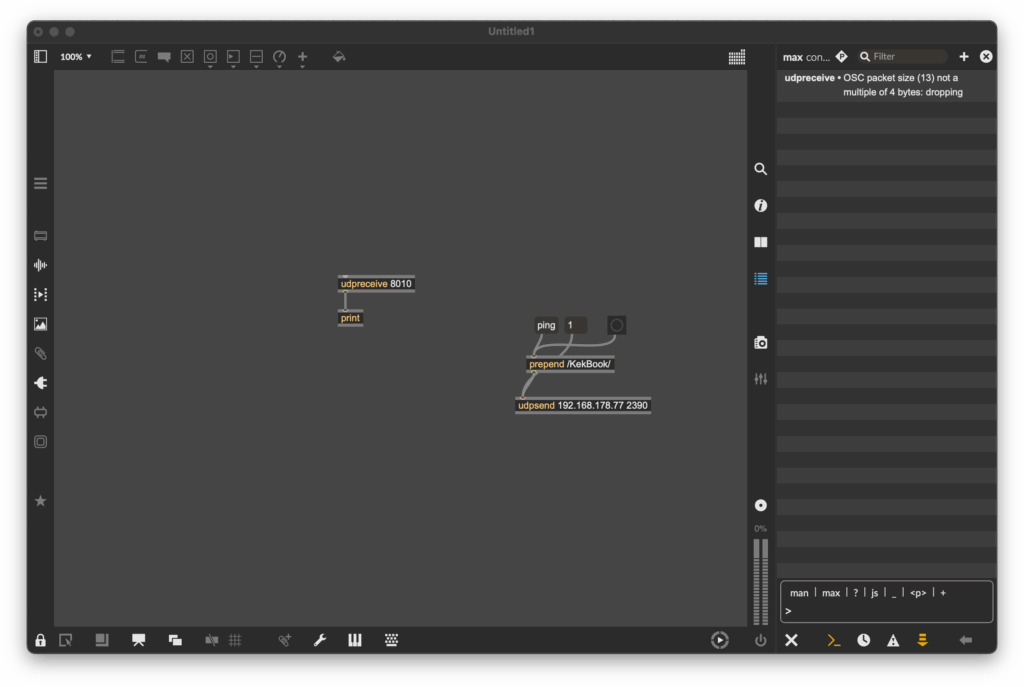
After getting the Arduino to encode Morse messages and send them to a connected Max patch (see the last blogpost), I took the next step. So far, I built a way to create messages, and a way to transmit them, but not everyone was able to simply read and understand morse code, so the next step was obvious: build a way the messages could be read in clear text. The idea was simple: after every message got “sent”, the Arduino would take the Morse code string and convert it into readable text.

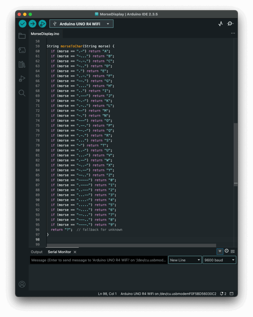
My first attempt was a long list of if statements, which worked, but I had hoped for an easier way to add and administrate different dot & dash combinations. Next I thought of using a switch statement to iterate through the combinations, but Arduino doesn’t support those, so I had to come up with a new idea. After searching on the internet, I came across a different solution, using arrays. So I rewrote it using arrays that mapped Morse code strings to letters. That gave me something that felt like a switch statement. It was now much cleaner, and easier to add custom combinations later.

Before:

After:

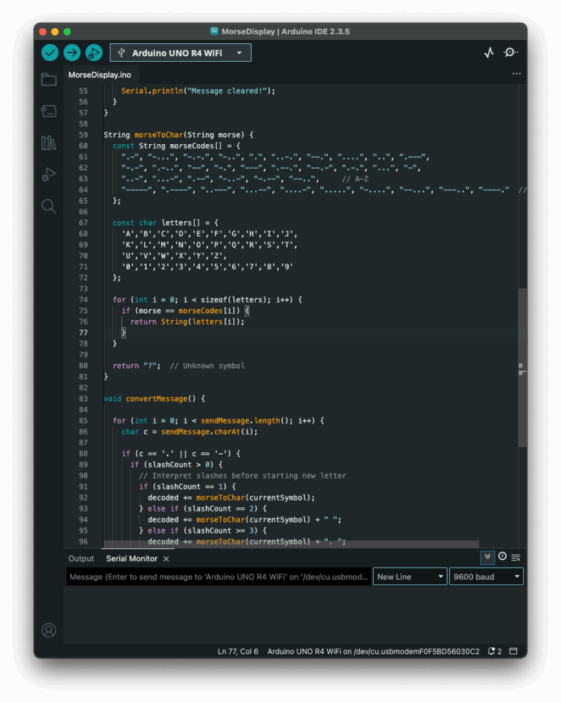
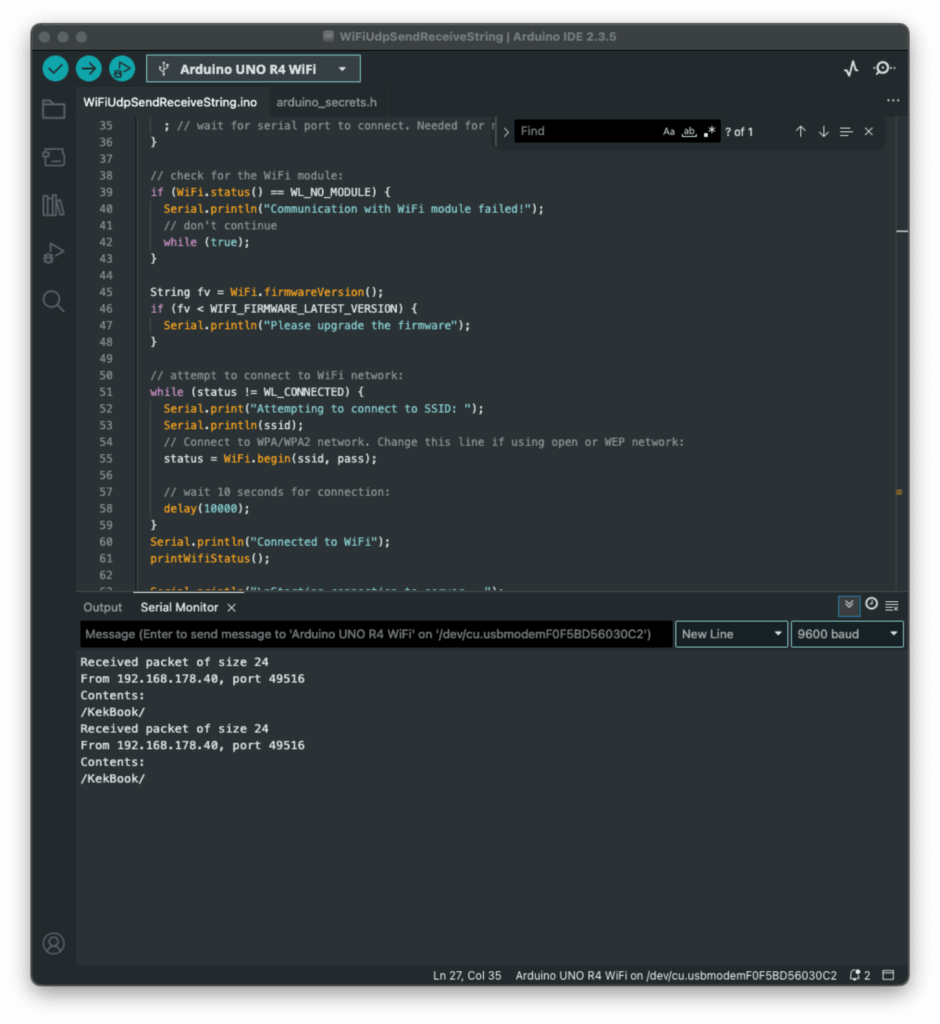
The decoding worked like this: one array was filled with all the Morse code symbols, and one with the matching letters. The code then iterated through the Morse message character by character, building a temporary substring that represented a single Morse symbol (like “.-” or “–“). Whenever it hit a slash (/), the program knew it had reached the end of one symbol. It then compared the collected substring to all entries in the Morse array. When it found a match, it took the corresponding index in the letter array to find the translation. That translated letter got added to the final decoded message string.

To figure out how many slashes were pressed, the code counted how many consecutive / characters appeared in the string. Each time it found a slash, it increased a counter. When a non-slash character came next (or the message ended), it used the number of counted slashes to determine the type of break:

  • One slash (/) meant a new letter started.
  • Two slashes (//) meant a new word started.
  • Three slashes (///) meant the start of a new sentence.
  • Four slashes (////) marked the end of the message. 

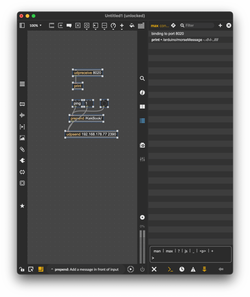
This system worked surprisingly well and gave me more control over formatting the final message. By using these simple separators, I could organise the output clearly and logically. Here is how the full print would look like with the translation.

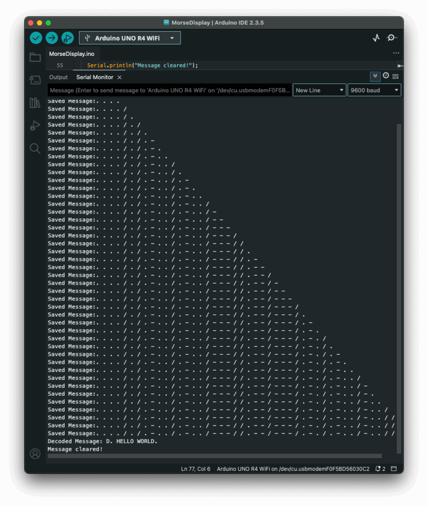
The result? A very basic but fully functional Morse communication device: input, output, transmission, and now decoding. Currently it is just displaying the message in the serial monitor, but I plan to make the message be displayed on the LED Matrix, on the Arduino, that way the message is readable to the user immediately. I also read online, that an Arduino can be connected to a web server, so I will probably test that out, since this way I could create smart devices for my room on my own.

Instructions

If you wanted to try it out yourself, here was what you needed:

  • An Arduino (compatible with Modulinos)
  • The three button Modulino
  • The latest sketch with decoding logic (I could share this if you were interested)

Not a lot to do, except plugging in the three button Modulino and uploading this sketch:

13 Adding UDP/OSC to Arduino

If you have read my previous blog post, the next step comes pretty natural. Just having one device creating and displaying morse code, defeats the purpose of this early way of communication. So I sat down, to set up a network communication between the Arduino and my laptop, which sounded easier than it was.

Since I had used OSC messages in countless classes before, I wanted to come up with a sketch, that could send those messages. Searching for a possibility to send this messages over WiFi, I started by looking at the examples, that were already provided by Arduino and I found something! Part of the WifiS3 library, there was a sketch, that showed how to send & receive UDP messages. Great! I uploaded the sketch and tried sending a message to the Arduino, using a simple Max patch. The message was received, although the response message wasn’t.

As you can see on the screenshot above, Max received a message, but it wouldn’t display its contents, since I had no idea what went wrong, I tried to adjust the message, so it would be a multiple of four, just like Max asked. But I just got another error message:

Still no idea what this error message was supposed to mean, but I kept trying. I reduced the length of the “message name string”, but without any success. I still got the same error message, as before, even though an even shorter message name wouldn’t have made any sense.

Defeated, I went to class the next day and talked about my problem with a fellow student. He brought to my attention, that Daniel Fabry had shared an example for the same thing last semester, which I knew worked, since I tried it in class, I just had forgotten about it. So I took a look at his sketch, which used an entirely different library. The code syntax was early identical, but the library was different. With my new knowledge, I adapted my code again and this time, it worked!

Now my Max patch could receive strings from the Arduino, great! As a next step, I updated my patch to actually replay the received morse code message. And my new version was done! Now messages could actually be sent wirelessly to other devices making actual communication possible.

This little detour into OSC & WiFi with Arduino really got me interested to explore this topic further. I am excited to find out the things that are possible using this technology.

Instructions

For the second version, you need:

  • an Arduino (capable of using Modulinos)
  • the three button Modulino
  • a Laptop with Max

Before uploading the sketch to the Arduino, you need to go into the “secrets.h” tab and enter your WiFi SSID (Name) and password. After this, go to the “sendIP” variable and change the Ip Address, to target your laptop. After applying these changes, upload the patch & build a simple UDP receive logic in Max, similar to the one you can see on my screenshots.

12 First Steps with Arduino

It’s not knowing that drives you mad. ~ Jenny Valentine

I read this quote somewhere on the internet and thought, this would be a great start to a new blog post, since it describes my struggles to start doing prototypes. I had no idea, where I should start or what I should do. With no clear direction in mind, I just started doing something. Since the start of this semester I have gotten really interested in Arduino. After the Arduino was introduced to us during class, I took one home and I have been wanting to create/ do something with it.

Developing a first Idea

Being a scout for over a decade, I have encountered multiple ways of encoding a message, mainly as riddles though. So the first idea I had was to create a device, that lets you encode a message. And the easiest one I thought of was morse code. I started, by attaching Modulino modules, pre-built circuit components like sensors or displays, to an Arduino. I used a three button module and the “pixel”, a board housing eight LEDs, one at first.

The idea was simple, by pressing the first button, the Arduino would receive a dot. Pressing the last one would send a dash and the middle one would be used to stand a slash, which is used in written morse code to communicate a break between letters, words and sentences. The first part was very simple, I created a sketch, that wrote the received button pushes as symbols into a string. I created this very easy and very fast.

Since I could write messages now, I needed a way to actually send the message and clear the message, so people could send a new one. First I tested if the Arduino would recognise multiple buttons being pressed at the same time, but it doesn’t. So I came up with the idea of incorporating an end signal, in my case, sending four consecutive pauses would result in the message being “send” or for now displayed and cleared.

Next, I wanted to be able to also display the message, at first I tried to attach the pixel Modulino and use its LEDs to display the message. This would make it easy to decipher between dots, dashes and breaks since each sign could be displayed clearly. Sadly, I couldn’t figure out, how to make the LEDs light up in the way I wanted them to. During most of the tests, they wouldn’t turn on at all or all of them would show the same color, with no difference between dot and dash. So I turned to a different solution, the buzzer, a Modulino that makes buzzing sound, with varying frequencies. Using the buzzer to output the message was much easier and I didn’t have any problems implementing it.

Current State

This was a lot of text now, since I forgot to take pictures I could attach here, but to showcase the first prototype, her is a short video showing the functionality of the current model. The video is in german but I think it will help illustrate, what I did and what the prototype does.

What’s next?

Developing this simple concept further I would want to make use of the wifi capabilities that the Arduino board I am using provides. This way a wireless connection between two Arduinos could be used to send and receive message. As an extra the LED Matrix of the Arduino could display the received letters in clear text so the person receiving doesn’t even have to know morse code, to decipher it.

A setup like this could be used in an escape room, in which two teams of kids have to work together, to open the door, but their only way of communication is to use morse code and send it using the two Arduinos. That way they could share information and complete the next riddle.

Instructions

For this first version, you don’t need a lot, for hardware you would need:

  • an Arduino (capable of using Modulinos)
  • the three button Modulino
  • the buzzer Modulino

After attaching the Modulinos tho the Arduino, you would just have to plug it into a computer and upload this sketch:

#include <Modulino.h>

ModulinoButtons buttons;
ModulinoBuzzer buzzer;

int frequency = 1000;
int duration = 1000;

int countB = 0;

bool button_a = false;
bool button_b = false;
bool button_c = false;

String message = String("Saved Message:");

void setup() {
  Serial.begin(9600);
  Modulino.begin();
  buttons.begin();
  buzzer.begin();
  pinMode(LED_BUILTIN, OUTPUT);
}

void loop() {
  if (buttons.update()) {

    if (buttons.isPressed(0)) {
      message = String(message + ". ");
      Serial.println(message);
      countB = 0;
    } else if (buttons.isPressed(1)) {
      message = String(message + "/ ");
      Serial.println(message);
      countB++;
    } else if (buttons.isPressed(2)) {
      message = String(message + "- ");
      Serial.println(message);
      countB = 0;
    }
  }

  if (countB >= 4) {
    pushMessage();
    message = String("Saved Message:");
    countB = 0;
    Serial.println("Message cleared!");
  }
}

void pushMessage() {
  for (int i = 0; i < message.length(); i++) {
    if (message[i] == '.') {
      digitalWrite(LED_BUILTIN, HIGH);
      buzzer.tone(frequency, duration);
      delay(150);
      digitalWrite(LED_BUILTIN, LOW);
      buzzer.tone(0, duration);
      delay(250);
    } else if (message[i] == '-') {
      digitalWrite(LED_BUILTIN, HIGH);
      buzzer.tone(frequency, duration);
      delay(500);
      digitalWrite(LED_BUILTIN, LOW);
      buzzer.tone(0, duration);
      delay(250);
    } else if (message[i] == '/') {
      delay(1000);
    }
  }
}

Lastly, I wanted to share some takeaways from my first “prototype”. Just starting to do something, with no clear goal in mind at first really sparked my motivation, to develop other little projects using the Arduino. Furthermore, I made small “prototypes” of code, that I test before incorporating them into the real thing. Aiming to understand how something works first, before using it. Lastly, I really need to take more pictures, so future blogposts are more interesting. ;D